Gaseous Diffusion Technology Developed
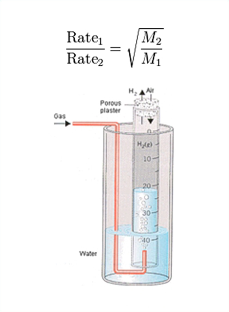
Gaseous diffusion is the result of a scientific principle discovered by Scottish scientist Thomas Graham who, in 1829, discovered that the rate at which gases diffuse is inversely proportional to the square root of their densities. According to Graham’s law, in gases with different isotopic molecules, the lighter isotopic molecule will have a slightly greater velocity than that of the heavier one. This principle is the basis of the separation of uranium by diffusion. Atoms and small molecules can move across a cell membrane and can also mix more rapidly with other gases by diffusion.
Graham tested his theory with a large glass tube of water, sealed at one end with plaster, but with holes large enough for H2 gas to enter or leave. When the tube was filled with H2 gas, the level of water in the tube slowly rose because the H2 molecules inside the tube escaped through the holes in the plaster more rapidly than the molecules in air could enter the tube. By studying the rate at which the water level in the tube changed, Graham was able to gather data on the rate at which different gases mixed with air.
Understanding Graham’s principle of diffusion is how scientists from Columbia University were able to separate U-235 in 1940, leading to the construction of the first large-scale gaseous diffusion plant in Oak Ridge, Tennessee in 1945.
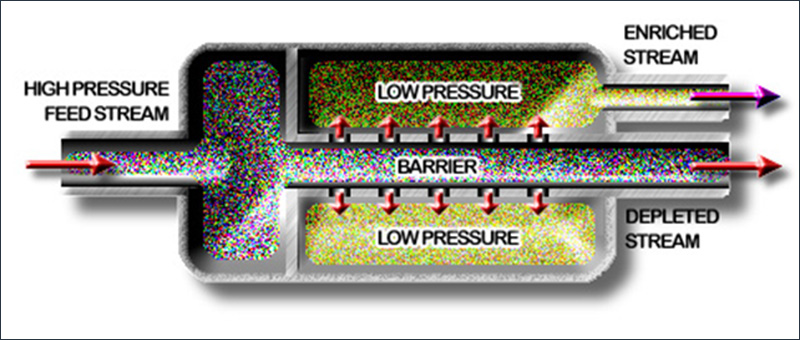
Two of the principal isotopes in natural occurring uranium are U-235 and U-238. Only .711% is the U-235 isotope, but it has the characteristics desired for power generation in most nuclear reactors, which require enriched U-235 at approximately 4-5% levels. The gaseous diffusion process uses UF6 at temperatures and pressures where it can be maintained as a gas. Similar to Graham’s experiment, a porous barrier is used to achieve separation. The (U-235)F6 molecule is less dense than the (U-238)F6 molecule, so it passes through a porous barrier more quickly. A pore size of less than two-millionths of an inch in diameter must be maintained to ensure diffusive flow.
Repeating the process of forcing uranium in the form of uranium hexafluoride through convertors made up of an assembly of porous barriers achieves highly enriched uranium.
Process Principles
Uranium, as it is found in nature, consists of several isotopes. The two principal isotopes are U-235 and U-238. Only 0.711% of the naturally occurring uranium is U-235; it is this isotope that possesses the characteristics desired for power generation in a nuclear reactor. Although some nuclear power generator reactor concepts permit the use of natural uranium, most reactor designs require fuels that have been enriched in U-235.
The gaseous diffusion process uses Uranium Hexafluoride (UF6) at temperatures and pressures where it can be maintained as a gas. The U(235)F6 molecule has slightly less mass than a U(238)F6 molecule and therefore can pass through a properly constructed barrier slightly more quickly than the U(238)F6 molecule. That propensity to pass through the barrier more quickly is the basis for the gaseous diffusion process.
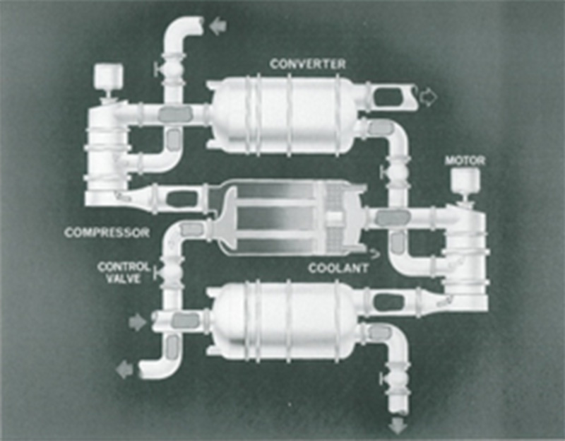
An assembly of barrier tubes used for uranium enrichment is called a converter. A converter and the associated compressor used to push the UF6 through the converter is called a stage. By cascading the separation stages together, the desired level of enrichment can be achieved. Because the separative capability per stage is so small, the exact number of stages required is determined by the enrichment needed. The pore size necessary for diffusive flow is so small that literally acres of barrier surface are required in a large production plant. The amount of barrier surface in each stage, or the number of porous tubes, depends on the required plant capacity.
A Diffusion Cascade
In the cascading of single stages, compressors push the UF6 through the inside of the barrier tube. About one-half of the gas is diffused through the barrier and is fed to the next stage; the remaining undiffused portion is recycled down. The diffused stream is slightly enriched with respect to U-235, and the stream that has not been diffused is similarly depleted with respect to U-235.
In a cascade, the flows at each stage were slightly different from the flows in stages immediately above or below. The converters that contain the largest flows and barrier area would be located at the normal assay (0.711% U-235) feed point. Those stages located above the feed point were referred to as the enriching section, and the stages located below the feed point were called the stripping section.
Economics and operating conditions dictated the use of large blocks or groups of process equipment, thus limiting the number of different basic sizes. To facilitate maintenance activities and to minimize resulting productivity losses, stages were grouped together to form cells. A cell has inlet and outlet block valves; it can be taken off-stream, bypassed, or shut down.