Uranium Enrichment
The Portsmouth Gaseous Diffusion Plant consists of the following basic process facilities:
- Three large process buildings housing the compressors and converters used for separation of U238 to U235.
- Product and tails withdrawal facilities located within the process buildings
- Feed plant used to convert UF6 to gas form and feed it to the process
- Transfer facility to fill customer cylinders
- Central control facility to provide high-level control of plant operations
The Portsmouth plant enriched uranium for the purposes of national defense and nuclear energy. This was accomplished with a process called gaseous diffusion whereby Uranium Hexafluoride (UF6) gas was forced through a series of porous barriers to reach a desired enrichment known as assay. (Click here to learn more)
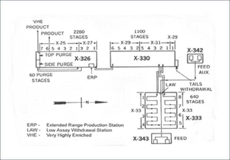
In the 1950s the United States was in the midst of the Cold War and building up its nuclear defense systems. The Portsmouth plant supported this effort by producing very highly enriched (VHE) uranium with an assay of 97.65% uranium-235 (U-235). To accomplish this level of enrichment, the UF6 gas passed through as many as over 4,000 isotopic stages which were housed in three huge process buildings: X-333, X-330 and X-326.
In the mid-1960s enrichment of VHE was suspended and the plant began enriching uranium at a lower assay for use in nuclear reactors aboard U.S. Navy ships and submarines and in civilian power plants. By the early 1990s, the plant’s primary mission was to produce low-enriched uranium assay between 3% and 5% for use in nuclear power plants throughout the United States and the world.
In 2001, enrichment activities were transferred to the Paducah Gaseous Diffusion Plant in Paducah, Kentucky and Portsmouth began to operate in “Cold-Standby” condition. In “Cold-Standby”, the Portsmouth plant was kept in a ready condition in which operations could be resumed in a period of 18-24 months if the need arose. In 2006, the plant transitioned from “Cold Standby” to Cold Shutdown” to prepare for the eventual decontamination and decommissioning cleanup project. On June 6, 2012, for the first time in more than 57 years, silence fell on the uranium enrichment cascade as the final cell was shut down in the X-326 building.
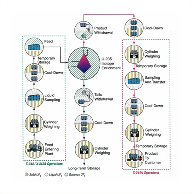
The Uranium Enrichment Process
- UF6 was introduced into the diffuser, or converter, in the X-333 Process Building and flowed along porous barrier tubes.
- Half of the gas was fed to the next higher stage and the remaining undiffused portion was recycled to the next lower stage.
- The diffused stream is enriched (enriched stream) and the undiffused stream is depleted of U-235 (depleted stream).
- The converter and compressor, working together to push the UF6, is called a cascade.
- The X-333 Building LAW station used compressors to promote the flow of UF6 through condensers to liquefy the material and transfer it to cylinders for storage at the X-344 and await shipment for customers.
- Waste material, or “tails”, in the X-330 Process Building, was withdrawn from its tails withdrawal facility.
- The A stream from the X-330 entered the X-326 and the B stream returned into the top X-29-6 cell stream in the X-330.
- Withdrawing the final product for use in nuclear reactors (uranium enriched in the 2 to 4.95% range) was done in either the X-326 or the X-333. Both used compressors to pressurize the UF6 stream and pass it through condensers, where it would be liquefied and withdrawn into 10-ton cylinders for storage, until it was transferred into 2 1/2 –ton cylinders for shipment to customers.
The Portsmouth Gaseous Diffusion Plant was capable of producing very highly enriched (VHE=97.65%U-235) product with its original cascade containing 4,020 isotopic stages. The five basic separative equipment sizes (compressors and converters) were used. The largest stages, which were driven by the largest (3300hp) motors, were located in the X-333 building and the smallest stages were located in the X-326.
Uranium Enrichment at the plant began with the feeding of UF6 at the X-342 Facility and later the X-343 Feed and Sampling Building. X-343 was not originally designed for this purpose, but replaced X-342 as the place UF6 was fed for enrichment when it was shut down for renovation to provide back-up feed and sampling capability.
Originally, ten-ton UF6 cylinders were received, weighed, and transferred to steam-heated vaporizers so the gaseous UF6 could enter the piping system. The feed vaporization equipment consisted of 12 steam vaporizers, connected to a separate cascade pipe line into the X-333 process building. Originally, the X-342 Facility supplied three types of feed material, varying in assay, to the process buildings. Later, the X-343 provided a range of feed options and assays.
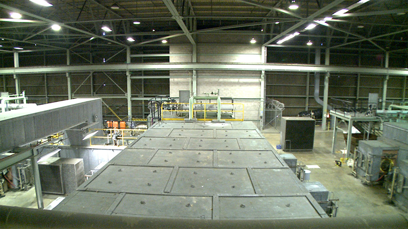
The next stage of the uranium enrichment process at the Portsmouth plant is the feed material entering the X-333 Process Building. The X-333 building housed the largest of the enrichment process equipment: eight units of 33 or “000” size (640) stages equipment. Since this building served as the entry point for all feed material into the cascade, the equipment had to be larger in order to handle the increased capacities.
The gaseous UF6 was introduced into the diffuser at X-333. Once the UF6 was pushed through the converter, control valves in the depleted piping to each compressor were used to control the inner stage flow pressures. Hot process gas was cooled by stage coolers in each converter. The cold recovery system in X-333 was designed to handle up to 5% U-235 assay material. Gas mixtures with high UF6 concentrations returned to a point of withdrawal and low assays flowed up to the cascade for purging in the side purge cascade.
In Building X330, cell X-29-1 was the bottom cell in the cascade so the depleted, or B, stream from this cell became the waste, otherwise known as the “tails”; this material was withdrawn at the tails withdrawal facility in the northeast corner of the building.
Cascade flow from the X-330 entered the X-326 building at the northeast corner and was directed into the first cell in unit X-27-1. X-29-6 was the top unit in the building, and the enriched, or A, stream from the top cell in the unit was sent to unit X-27-1 in Building X-326. The B stream from X-27-1 returned into the top X-29-6 cell stream. A and B streams crossed various paths in the X-326 cascade and purged to the top or side purge.
Withdrawing the final product was done at the top product station, located in the X-326 building with two lines; one withdrew the top assay and the other withdrew a stream that could be valved into other parts of the cascade. Once withdrawn into 5 inch cooling cylinders, the UF6 became a solid.
The largest demand for commercial nuclear reactor material was in the 2 to 4.95% enrichment range. Two extended range production stations (ERP) and the low-assay withdrawal station (LAW) were designed for that purpose. UF6is normally withdrawn into cylinders for shipment to customers.
The tails withdrawal facility in the X-330 building was primarily used to withdraw waste, but was made so two different assays could be drawn simultaneously.
Power Consumption
The Portsmouth Gaseous Diffusion Plant received its electrical power from the compilation of 15 investor-owned power companies of the Ohio River Valley that developed the Ohio Valley Electric Corporation (OVEC) for the purpose of delivering electrical power to the plant.
There were two power plants built to generate enough power and interconnect with the OVEC companies to deliver to the plant. The agreement signed between the two plants and OVEC in 1956, called for continuous delivery of 1,950 megawatts (MW) of electrical power to Portsmouth.
Power Plants of the Portsmouth Gaseous Diffusion Plant
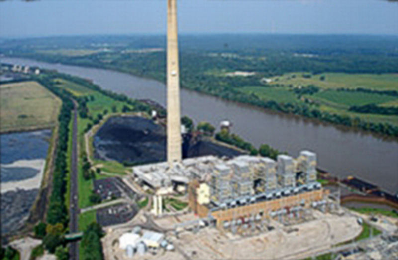
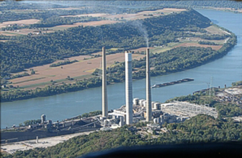
The Kyger Creek Power Plant, located in Cheshire, Ohio on the Ohio River, was built, owned and operated by OVEC. It received the majority of its 214MW units of coal powered energy from river barges. It had the total design capacity of 1070MW.
The Clifty Creek Power Plant, in Madison, Indiana was built, owned and operated by Indiana-Kentucky Electric Corporation (IKEC), an OVEC subsidiary. It produced six coal-fired 214MW units, but had the capacity to produce 1284MW. Like Kyger Creek, it used a majority of its coal from the Ohio River.
In 1969, American Electric Power (AEP) built the Don Marquis Substation to provide an interconnection network between OVEC and several other entities. The substation contained three transformers, much high voltage switchgear, circuit breakers and a 345kV yard with five lines that tied between the site’s switchyards and surrounding facilities.
Water Consumption
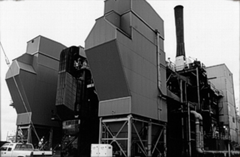
The plant utilized six million gallons of water per day for water cooling systems in cooling towers, process buildings and as steam. In the X-333 cold recovery system, a condenser and two tanks were cooled with water. Steam was used at the plant for the enrichment process, to heat buildings, and to clean equipment. The X-600 Steam Plant was located near the southern end of the plant and contained three boilers fired with coal and produced 125-psi saturated steam. Water used at the plant was either taken from underground wells and the Scioto River, or it was treated at the X-611 Water Treatment Plant and supplied directly from the X-605A Sanitary Wells and used for sanitary purposes.
Water Treatment Facility
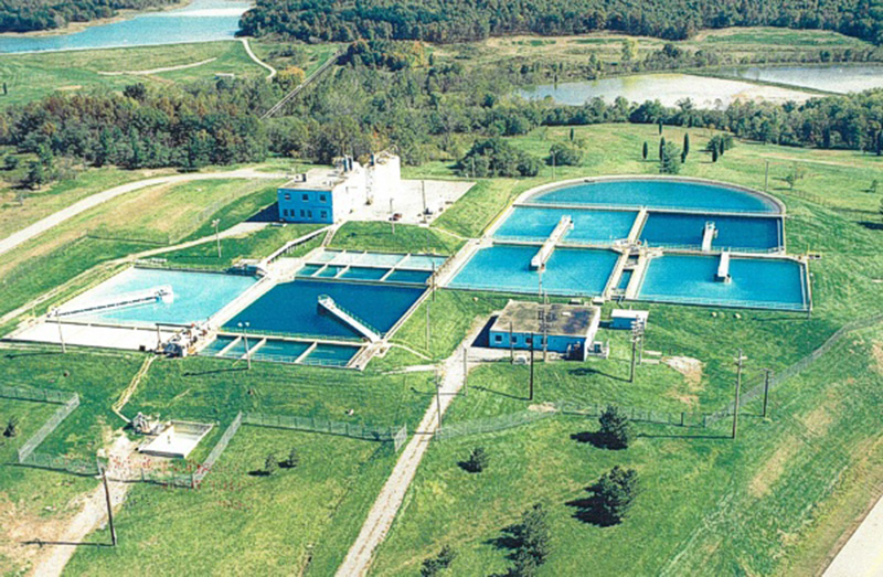
The X-611 Water Treatment Plant provides chlorinated, high quality water suitable for use at the plant. It had the capacity to process 40 million gallons per day, but usually processed over 10 million gallons of makeup water daily for the plant’s recirculating cooling water system. After it was taken from the Scioto River or well fields near the river, it was treated to remove bicarbonates to prevent damage to heat transfer equipment and kill harmful bacteria. The water treatment process was based on conventional water treatment techniques, which include softening, coagulation, flocculation, sedimentation, filtration, chlorination, and pH adjustment.